| Fit cable ties in the original positions when installing. |
|
|
|
| – |
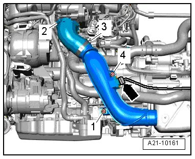
Disconnect electrical connector -arrow- and move electrical wires clear. |
 WARNING
| Hot steam/hot coolant can escape - risk of scalding. |
| The cooling system is under pressure when the engine is hot. |
| Cover filler cap on expansion tank with a cloth and open carefully to dissipate pressure. |
|
| – |
Open filler cap on expansion tank. |
| – |
Remove front exhaust pipe with catalytic converter → Chapter. |
| – |
Remove right front wheel. |
|
|
 |
| – |
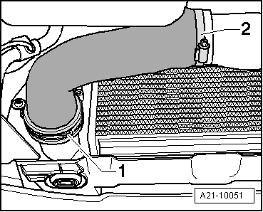
Remove air pipe -item 1 and 2-. |
|
|
 |
| – |
Remove bolt -1- and take out air pipe downwards. |
|
|
|
| – |
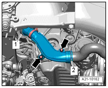
Remove air pipe (lift clips -items 1 and 2-). |
|
|
 |
| – |
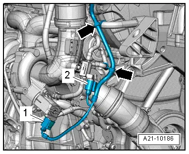
Separate electrical wiring connections -1 and 2- and place electrical wiring to one side -arrows-. |
|
|
 |
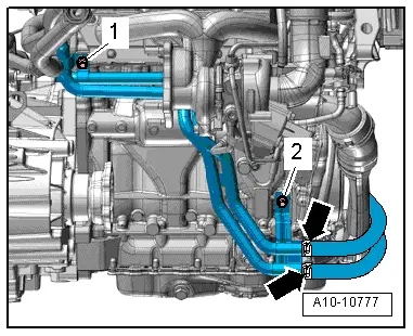
| Vehicles with auxiliary heater: |
| – |
Unscrew bolts -1 and 2- and move coolant pipes to the left. |
|
|
 |
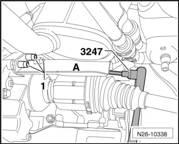
| Vehicles with four-wheel drive: |
| – |
Unscrew bolts -1- for heat shield -A- above right axle shaft using hexagon key extension, 8 mm -3247-. |
|
|
 |
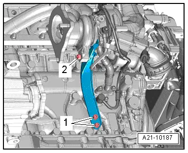
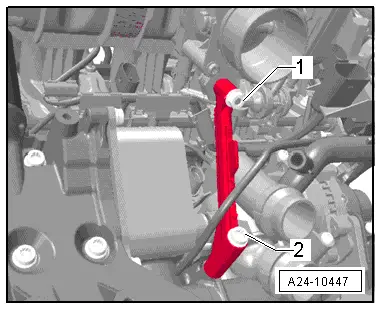
| – |
Remove bolts -1 and 2- and detach support for turbocharger. |
|
|
 |
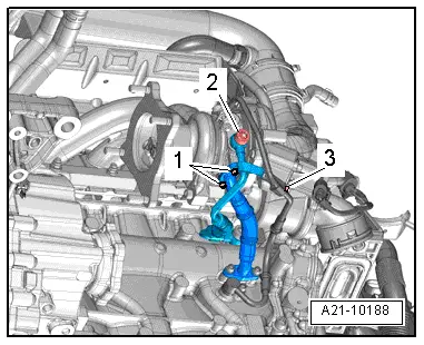
| – |
Remove banjo bolt -2- and move coolant pipe clear to one side. |
| Vehicles with front-wheel drive |
| – |
Remove bolts -1- on oil return pipe. |
| Vehicles with four-wheel drive: |
| – |
Undo and remove bolts of oil return line at crankcase. |
| – |
Remove bolt -3- on oil supply pipe. |
| – |
Only vehicles with sound generator: Remove charge air duct to sound generator. |
|
|
 |
| – |
Detach connector from inlet camshaft control valve 1 -N205--1-. |
| – |
Disconnect electrical connectors at ignition coils and place wiring harness to one side. |
|
|
 |
| – |
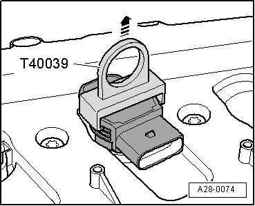
Remove ignition coils using puller -T40039-. |
|
|
 |
| Engine codes BZB, CAWA, CAWB, CGYA, CDAA: |
| – |
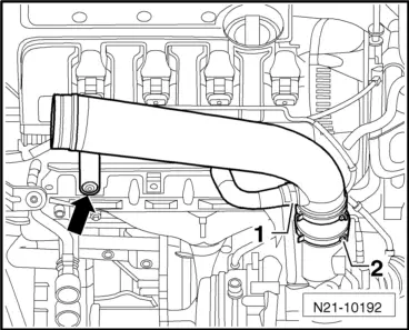
Press release tabs, detach air hose -1- and swivel to side. |
| – |
Unscrew bolt -arrow- for air pipe. |
| – |
Loosen hose clip -2- and remove air pipe. |
|
|
 |
| – |
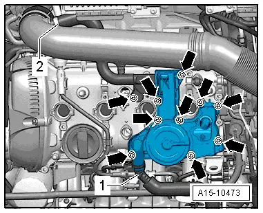
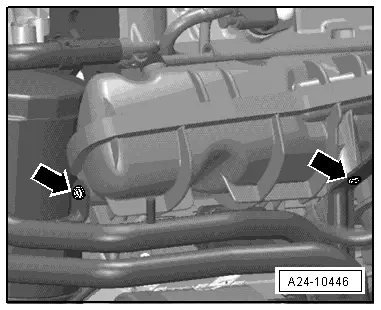
Disconnect crankcase breather hose -1-. |
| – |
Remove bolts -arrows- and remove crankcase breather. |
|
|
 |
| Engine codes CBFA, CCTA, CCTB: |
| – |
Disconnect crankcase breather hose -1-. |
| – |
Unscrew bolts -arrows-. |
|
|
|
| – |
Unscrew bolt -arrow- for air pipe. |
| – |
Loosen hose clip -2- and remove air pipe together with crankcase breather. |
WARNING
| Fuel supply line is pressurised. Wear eye protection and protective clothing to avoid possible injury and skin contact. Before loosening hose connections, wrap a cloth around the connection. Then release pressure by carefully pulling hose off connection. |
|
|
|
|
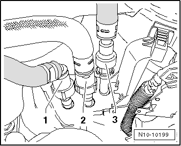
| – |
Detach lines -1 to 3- from the fuel transfer point. |
| |
2) Vacuum line (only CBFA, CCTA, CCTB) |
|
|
 |
| – |
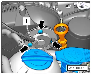
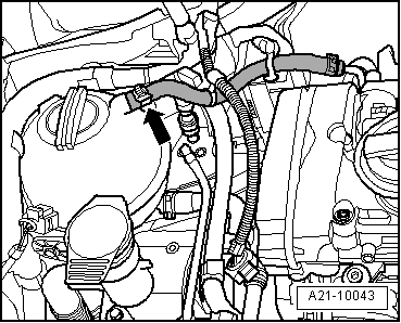
Disconnect coolant line to coolant expansion tank -arrow-. |
|
|
 |
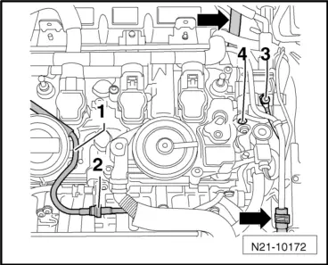
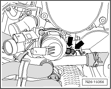
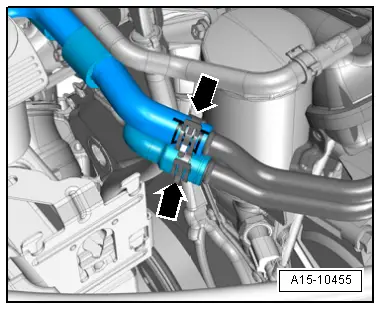
| – |
Remove coolant hoses -arrows- from coolant pipe. |
| – |
Unbolt earth cable -3- and slacken bolt -4-. |
|
|
 |
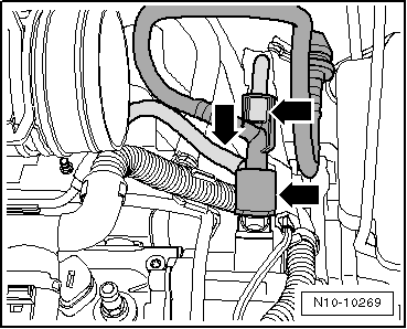
| – |
Pull off vacuum hoses -arrows-. |
|
|
 |
| – |
Loosen bolts -1…4- and remove heat shield together with coolant pipe. |
| – |
Remove oil supply pipe from turbocharger -4-. |
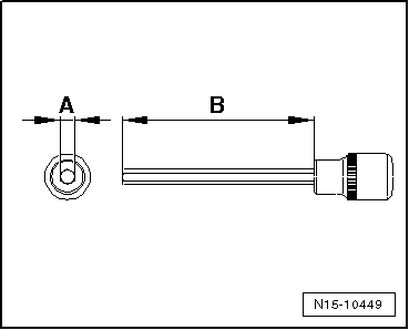
 Note |
|
 |
| On 2.0 l engines, unscrew bolt -2- from heat shield using 6 mm -A- hexagon socket. The hexagon must be at least 5 cm -B- long. A socket which tapers to 6 mm at the tip is too thick. |
|
|
 |
| – |
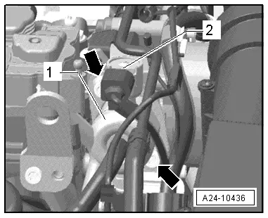
Pull electrical connector -2- from fuel pressure regulating valve -N276-. |
|
|
 |
| – |
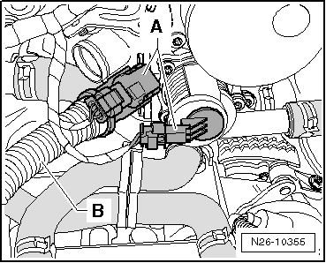
Pull connector -A- and hose -B- from secondary air inlet valve -N112-. |
|
|
 |
| – |
Loosen coolant pipe by unscrewing bolts -arrows-. |
| – |
Pull coolant hose from lateral union on cylinder head. |
|
|
 |
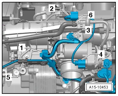
| – |
Disconnect electrical connectors -1 … 4-. |
| – |
Place electrical cable -5- to one side. |
| – |
Detach vacuum line -6- leading to activated charcoal filter. |
|
|
 |
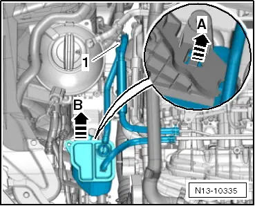
| – |
Pull off breather line -1-, release activated charcoal filter -A- and remove upwards -B-. |
|
|
 |
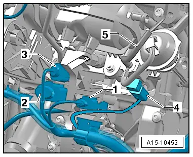
| – |
Disconnect electrical connectors -1- and detach connectors from retainer. |
| – |
Disconnect electrical connectors -2 … 4-. |
|
|
 |
| – |
Detach coolant pipe from intake manifold; to do so, unscrew bolts -arrows-. |
|
|
 |
| – |
Remove intake manifold support (remove securing nut -1- and bolt -2-). |
|
|
 |
| – |
Disconnect coolant hoses -arrows- and move clear. |
|
|
 |
| – |
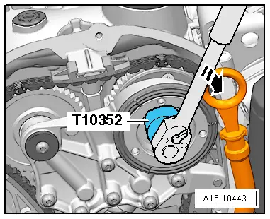
Unscrew bolts -arrows- and remove inlet camshaft control valve 1 -N205-. |
 Caution
| The timing valve has a left-hand thread. |
|
|
|
|
| – |
Remove control valve using assembly tool -T10352- (engine codes CCZA, CCZB, CCZC, CCZD, CDAA, CDAB: assembly tool -T10352/1-) in direction of -arrow-. |
|
|
 |
| – |
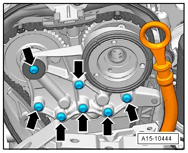
Remove bolts -arrows- and detach bearing saddle. |
|
|
 |
| – |
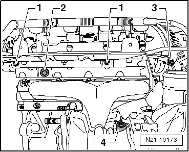
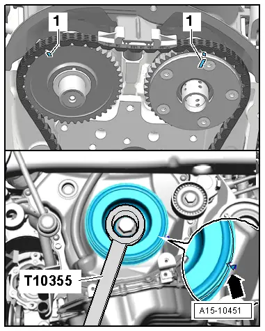
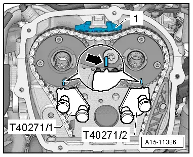
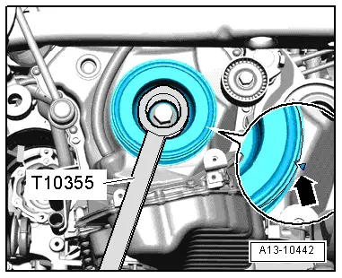
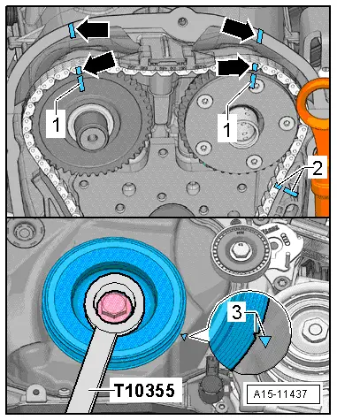
Turn vibration damper to »TDC« position -arrow- using counterhold -T10355-. |
| l |
Notch on vibration damper must align with arrow marking on cover for timing chains (bottom). |
| l |
The markings -1- on the camshafts must face upwards. |
|
|
 |
| – |
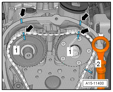
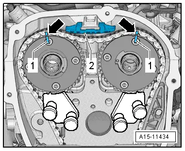
Mark positions of chain sprocket markings -1- on camshaft timing chain and cylinder head -arrows- using a permanent felt tip marker. |
| – |
Also mark alignment of camshaft timing chain -2- relative to guide rail of camshaft timing chainusing a permanent felt tip marker. |
|
|
 |
| – |
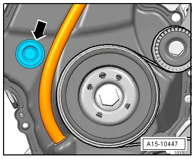
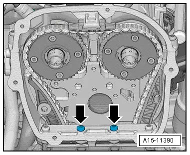
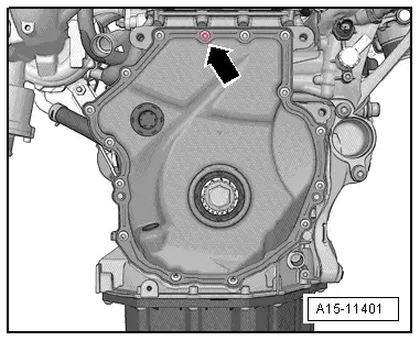
Remove sealing plug -arrow-. |
|
|
 |
| – |
Unscrew bolts -arrows-. |
|
|
 |
| Depending on model, two different chain tensioners may be installed: |
| – |
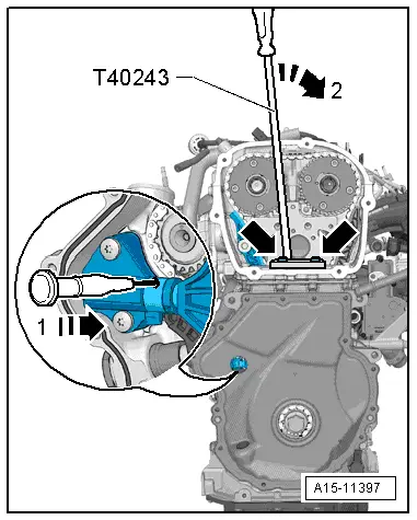
Screw in valve lever -T40243--arrows-. |
| – |
Insert scriber or suitable screwdriver in hole of chain tensioner in direction of -arrow 1- and lift locking element. Then, slowly push valve lever -T40243- in -direction of arrow 2- and hold it in that position. |
|
|
 |
| – |
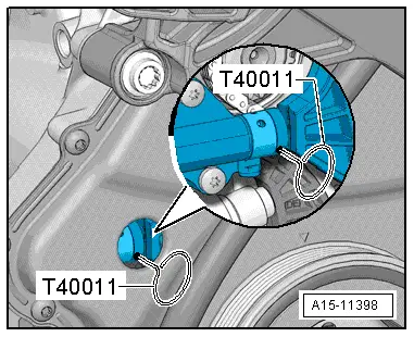
Secure chain tensioner with locking pin -T40011-. |
|
|
 |
| – |
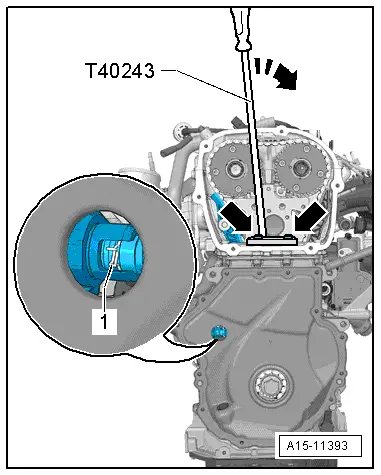
Screw in valve lever -T40243--arrows-. |
| – |
Press together circlip -arrow- of chain tensioner. Then, slowly push valve lever -T40243- in -direction of arrow- and hold it in that position. |
|
|
 |
| – |
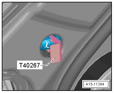
Secure chain tensioner with locking pin -T40267-. |
| – |
Remove valve lever -T40243-. |
|
|
 |
| – |
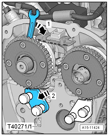
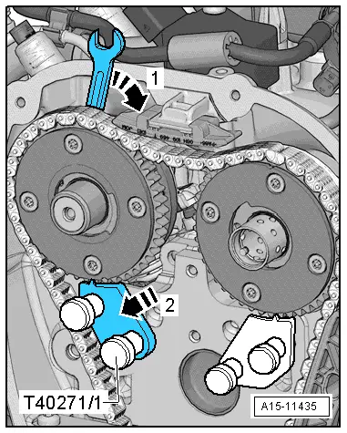
Bolt camshaft clamp -T40271/2- to cylinder head and insert it in -direction of arrow 2- between splines of chain sprocket. If necessary turn inlet camshaft in -direction of arrow 1- using spanner. |
|
|
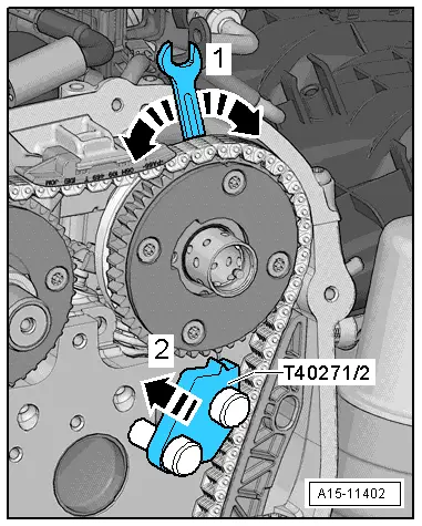 |
| – |
Remove bolt -1- and guide tensioning rail -2- downwards. |
|
|
 |
| – |
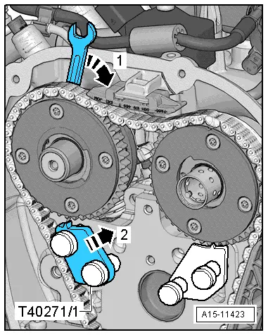
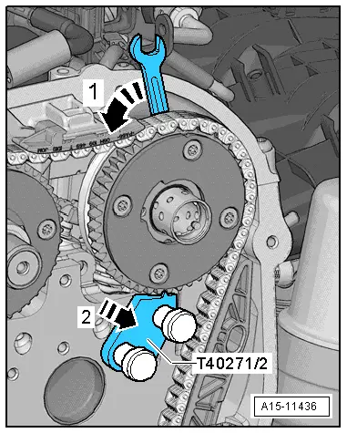
Bolt camshaft clamp -T40271/1- to cylinder head. |
| – |
Turn exhaust camshaft in -direction of arrow 1- using spanner and insert camshaft clamp -T40271/1- in -direction of arrow 2- between splines of chain sprocket. |
|
|
 |
| – |
Use screwdriver to release catch and press off top guide rail -1- forwards. |
| – |
Remove camshaft timing chain from camshaft sprockets. |
Caution
| Avoid damage to valves and piston crowns. |
| Do not turn the crankshaft after the camshaft timing chain has been removed from the cylinder head. |
|
|
|
 |
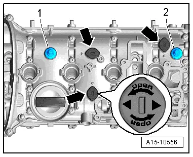
| – |
Turn sealing plugs -arrows- 90° anti-clockwise -arrow- and remove. |
|
|
 |
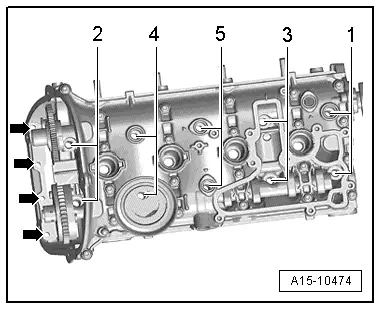
| – |
Unscrew bolts -arrows-. |
| – |
Unscrew cylinder head bolts using polydrive bit and socket -T10070- in sequence -1 … 5-. |
Note
| t |
Make sure all hoses/pipes and wiring on component are removed. |
| t |
Ensure tensioning rail and guide rail are not damaged when lifting off cylinder head. |
| – |
Place cylinder head onto soft surface (foam plastic). |
Caution
| Avoid damage to sealing surfaces. |
| t |
Carefully remove sealant residue from cylinder head and cylinder block. |
| t |
Ensure that no long scores or scratches are made on the surfaces. |
| Avoid damage to cylinder block. |
| No oil or coolant must be allowed to remain in the blind holes for the cylinder head bolts in the cylinder block. |
| Ensure that cylinder head gasket seals properly: |
| t |
Carefully remove remains of emery and abrasives. |
| t |
Do not remove new cylinder head gasket from packaging until it is ready to be fitted. |
| t |
Handle the cylinder head gasket very carefully to prevent damage to the silicone coating or the indented area of the gasket. |
| Avoid damage to open valves. |
| When installing an exchange cylinder head, the plastic protectors fitted to protect the open valves should not be removed until the cylinder head is ready to be fitted. |
| Avoid damage to valves and piston crowns after working on valve gear. |
| Turn the engine carefully at least 2 rotations to ensure that none of the valves make contact when the starter is operated. |
|
Note
| t |
Renew bolts tightened with specified tightening angle. |
| t |
Renew self-locking nuts as well as gaskets, seals and O-rings. |
| t |
When installing a replacement cylinder head, the contact surfaces between hydraulic compensation elements, roller rocker fingers and cams must be oiled before installing the camshafts. |
| t |
Hose connections and air duct pipes must be free of oil and grease before assembly. |
| t |
In order to be in a position to securely attach the charge air hoses on their connections, the worm screws of the used hose clips have to the sprayed with penetrating spray before installing. |
| t |
When cylinder head or cylinder head gasket is renewed, the entire coolant and the engine oil must be changed. |
| Procedure for new cylinder head |
|
|
 |
| – |
Mark alignment of camshaft sprockets relative to camshaft clamp -T40271/1- and camshaft clamp -T40271/2--arrow-. |
|
|
|
| – |
Turn inlet camshaft in -direction of arrow 1- using spanner, remove camshaft clamp -T40271/2- in -direction of arrow 2- from between splines of chain sprocket and bring camshaft into rest position. |
| – |
Remove camshaft clamp -T40271/2-. |
|
|
 |
| – |
Turn exhaust camshaft in -direction of arrow 1- using spanner, remove camshaft clamp -T40271/1- in -direction of arrow 2- from between splines of chain sprocket and bring camshaft into rest position. |
| – |
Remove camshaft clamp -T40271/1-. |
| – |
Transfer the previously marked markings from the old camshafts onto the new camshafts. |
|
|
 |
| – |
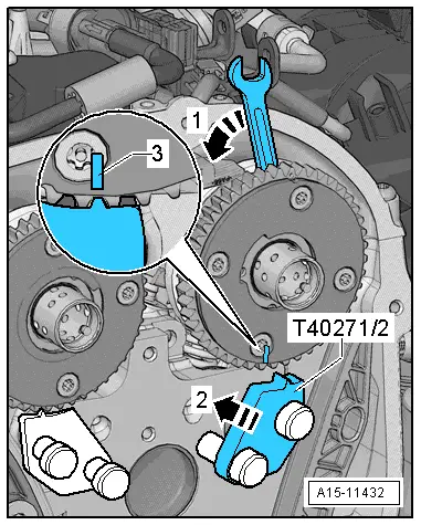
Bolt camshaft clamp -T40271/2- to cylinder head. |
| – |
Turn inlet camshaft in -direction of arrow 1- until marking -3- aligns with camshaft clamp -T40271/2-. |
| – |
Insert camshaft clamp -T40271/2- in -direction of arrow 2- between splines of chain sprocket. |
|
|
 |
| – |
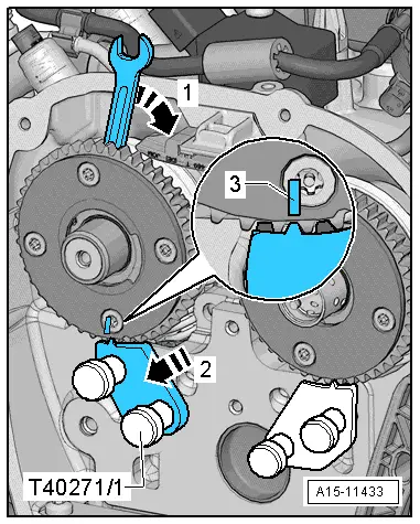
Bolt camshaft clamp -T40271/1- to cylinder head. |
| – |
Turn exhaust camshaft in -direction of arrow 1- until marking -3- aligns with camshaft clamp -T40271/1-. |
| – |
Insert camshaft clamp -T40271/1- in -direction of arrow 2- between splines of chain sprocket. |
|
|
 |
| – |
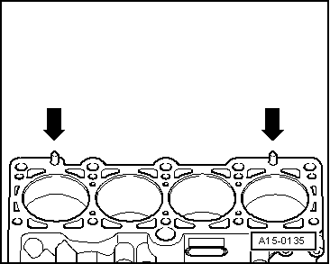
Position cylinder head gasket. |
| t |
Note position of centralising pins in cylinder block -arrows-. |
| t |
Check installation position of cylinder head gasket. The part number should be legible from the inlet side. |
WARNING
| When turning the crankshaft, ensure that no components are damaged by the timing chain. |
|
| – |
If crankshaft is turned in the meantime, position piston of No. 1 cylinder at TDC and turn crankshaft back slightly. |
| – |
Insert and hand-tighten cylinder head bolts. |
| – |
Tightening sequence for cylinder head → Fig.. |
Note
| After repair work it is not necessary to retighten the cylinder head bolts. |
WARNING
| When turning the crankshaft, ensure that no components are damaged by the timing chain. |
|
|
|
 |
| – |
Turn vibration damper to „TDC“ position -arrow- using counterhold -T10355-. |
| l |
Notch on vibration damper must align with arrow marking on cover for timing chains (bottom). |
|
|
 |
| – |
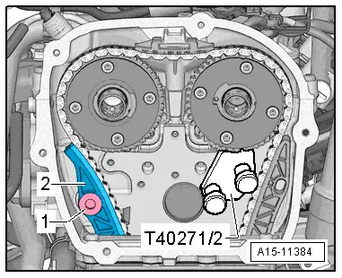
Fit camshaft timing chain on chain sprockets. To do this, align markings on chain links -arrows-with markings on chain sprockets -1-. |
| – |
Install upper guide rail -2-. |
|
|
 |
| – |
Turn exhaust camshaft in -direction of arrow 1-, remove camshaft clamp -T40271/1- in -direction of arrow 2- from between splines of chain sprocket and relieve tension from camshaft. |
| – |
Remove camshaft clamp -T40271/1-. |
|
|
 |
| – |
Move tensioning rail -2- upwards and screw in bolt -1-. |
|
|
|
| – |
Turn inlet camshaft in -direction of arrow 1-, remove camshaft clamp -T40271/2- in -direction of arrow 2- from between splines of chain sprocket and relieve tension from camshaft. |
| – |
Remove camshaft clamp -T40271/2-. |
|
|
 |
| – |
Check valve timing. Markings on camshaft timing chain and cylinder head -arrows- must align with markings on chain sprockets -1-. |
| – |
Markings on camshaft timing chain and on guide rail of camshaft timing chain -2- must also align. |
| – |
Notch on vibration damper must align with marking on lower timing chain cover -3-. |
|
|
 |
| – |
Attach bearing saddle and screw in bolts -arrows- hand-tight. |
| – |
Depending on model, remove locking pin -T40011- or locking pin -T40267-. |
| – |
Tighten bolts -arrows- for bearing saddle → Chapter. |
|
|
|
| – |
Install timing valve → Item. |
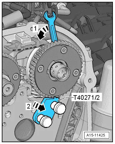
| – |
Use spanner to turn inlet camshaft in direction of -arrow- and fit timing chain. |
| Remaining installation steps are carried out in reverse sequence; note the following: |
| – |
Fill cooling system with fresh coolant → Chapter. |
|
|
 |
Chain drive |
|